SWD Registered Lightning Link (RLL) Consolidated Information
Summary of what is needed to make the RLL Work
- BUY A KNS LIGHTNING LINK PROTECTOR
- Remove material from the lower so the ears of the RLL don’t bind (if necessary)
- Remove .040 off the rear upper lug to accommodate the KNS protector (if necessary)
- Cut the BCG to .380” from the rear (if necessary)
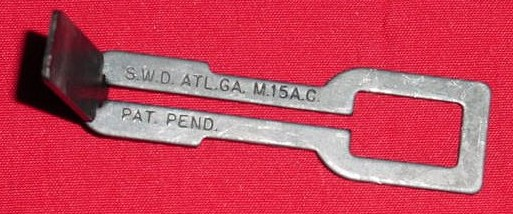
- Determine the paddle size based on headspace (instructions below)
- See Tips section below – some users remove receiver material near buffer tube (if necessary)
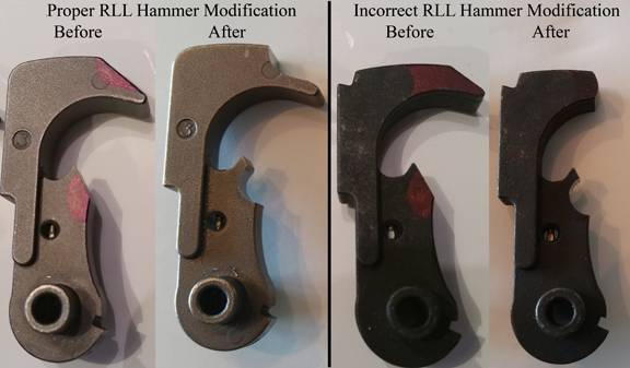
- Recommend modifying hammer to avoid contact with link and trigger slap
Quarterbore site info (http://www.quarterbore.com/nfa/lightninglink.html)
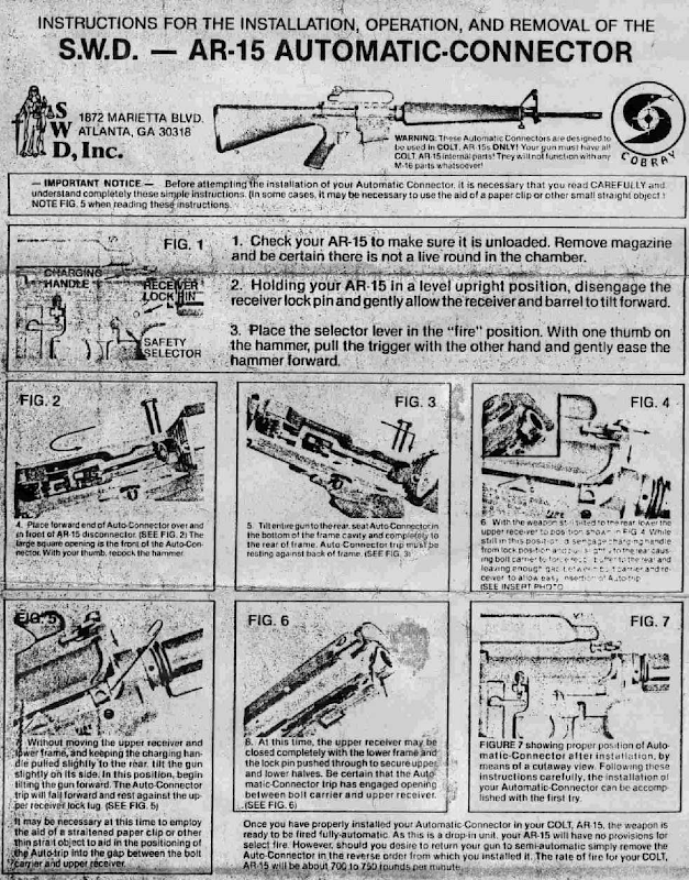
The SWD Lightning Link (SWD Auto Disconnector or Auto Connector) is one of those unique solutions where someone happened to look at the operation of the AR-15 and how the various parts of the operating systems work together to find an easy way to convert a semi-automatic firearm into a fully automatic weapon. Please understand that it is illegal for a US Citizen to build one of these units without special licenses and the purpose of this page is to discuss how the Lightning Link works and not to provide guidance on how to build one.
In normal semi-auto operation the hammer is cocked by a rearward movement of the bolt carrier, as the carrier moves forward, the hammer is caught and held in the cocked position by the sear located on the forward part of the trigger catching in the sear notch, on the hammer. If you hold the trigger after a shot’s fired the sear will not catch in the hammer’s sear notch when the hammer cocks because the sear is depressed below the arc of the hammer notch.
This happens because the trigger is being held back by the hook on the disconnector which is tipped forward and in position to catch the hammer, stopping it from following the bolt carrier forward. When the trigger is released, it allows the hammer to slip from under the disconnector hook and to be caught by the trigger sear in the hammer sear notch. Making it necessary to pull the trigger for each shot. As long as the trigger is held back, the sear is held below the arc of the hammer notch. The only thing holding the hammer in the cocked position is the disconnector. The Lightning Link accomplishes full-auto fire by pulling the disconnector to the rear forcing it to release the hammer.
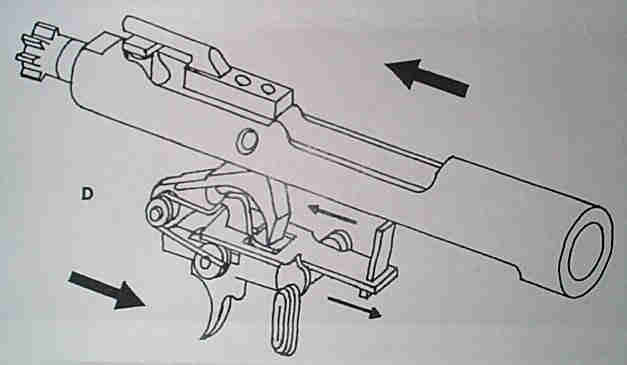
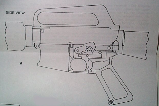
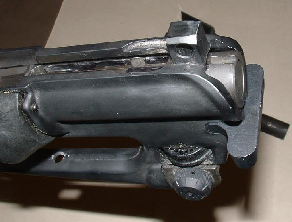
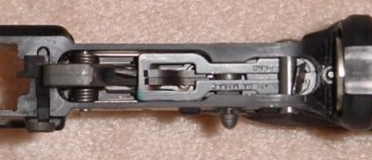
The lightning link is installed by removing the rear take down pin and pivoting the upper by the front pivot pin. The lightning link is then dropped inside the lower with the paddle pointing up, making sure the LL loop goes in front of the disconnector hook as shown in the image above. I have read that the gun might be tricky to close as the paddle has to fit inside the gap between the upper and the bolt carrier. One trick that might help is to point the muzzle of the rifle down as you close the upper receiver. I also understand that sometimes it may be necessary to shave some steel from the carrier to make room for the link. Care must be taken not to remove too much material as obviously this would affect the operation of the link.
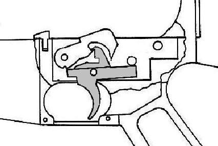
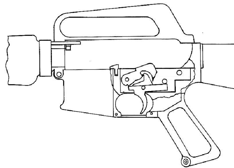
In operation the take-down pin post acts as a fulcrum point. When the bolt carrier strikes the top of the links paddle and the lower end is rocked to the rear, moving the body of the link backward about 1/16 inch, releasing the hammer from under the disconnector hook.
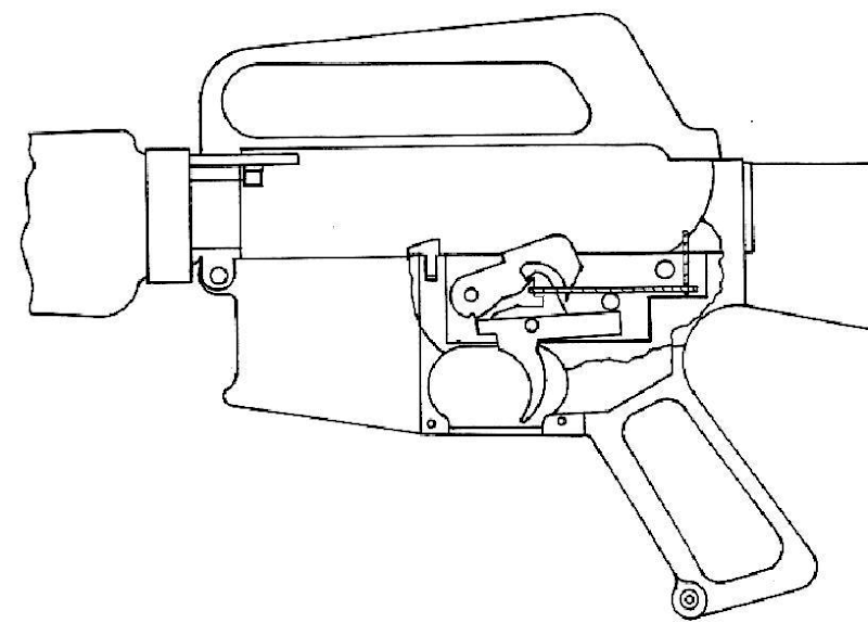
As long as the trigger is held back the rearward movement of the bolt carrier will cock the hammer under the disconnector hook. The forward movement of the carrier will strike the upright paddle of the link just as the bolt locks in battery, releasing the hammer, and firing the weapon. When the trigger is released, the sear will stop the hammer in the cocked position negating the operation of the disconnector and the Lightning Link.
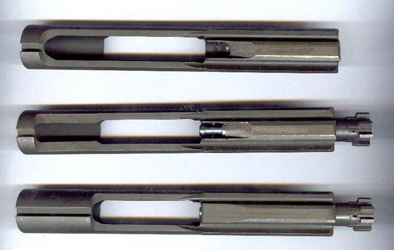
The rounded AR-15 Carrier (top) has more material at the rear of the carrier as can be seen in the photo above when you compare it to the Colt SP-1 style carrier in the middle.. When you try to use one of the top carriers with a Lightning Link, the link will hit the rounded edge at the rear of the carrier before the carrier closes into battery allowing the rifle to fire. NOTE: This is a very dangerous situation and anybody with a link needs to read the timing section that follows to prevent a KABOOM!
The SP-1 carrier, the one in the middle, with it’s square back is the carrier that the lightning link was designed for. This style carrier allows the bolt to nearly close before the link is hit tripping the disconnect. A person would still want to check their timing before using live ammo but this is the carrier that will work with the link.
The bottom carrier in the photo above, the M-16 carrier will not work with the link but I have included it on this scan so you can see how the SP-1 carrier was made by cutting down an M-16 carrier. It would be possible to make a SP-1 type carrier from a M-16 carrier or simply mill an AR-15 carrier to the proper profile. Also, following is a photo of the newest style Colt “Open” Carrier that was designed specifically to prevent the use of the Lightning Link. As you can see, the Colt “Open” carrier has no trip surface that will work with the link.
9mm Bolt Groups and the SWD Auto Connector

Top: Normal RRA M-16 Compatible 9mm Bolt
Bottom: Modified RLL 9mm Bolt
From the discussion of the 223 bolts above, it should be fairly clear what is needed to make other bolts work with the SWD Auto Connector. In the photos above I am showing my RRA 9mm bolts. The top bolt is a new RRA 9mm bolt that will work with an AR-15 or M-16. The rounded area in the slot in the bottom of the bolt is designed for a GI Auto Sear to function and the trip surface is in the proper location for the M-16 or DIAS.
To make a 9mm bolt compatible with the lightning link, one needs to mill the carrier as shown at the bottom of the photo above. In essence, all that is done is to mill the carrier to emulate the rear surface of the SP1 carrier as shown in the photo above of the 223 carriers. When performing this work, it is essential to test the timing of the Lightning Link and the directions that follow will give you an idea of how to confirm your timing is acceptable.
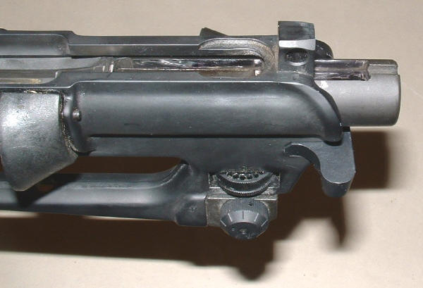
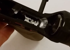
Following are two photos that show the 9mm bolt that was modified for the Lightning Link inserted into a upper receiver. The top photo shows the 9mm bolt pulled to the rear while the bottom photo shows the gap between the 9mm bolt and the rear takedown lug that is normal with a carrier designed to be used with the link..png)
Registered Lightning Link Timing made easy
Provided by Dano523 of AR15.com
With the link in the rifle, hold the trigger back and cock the action, then slowly ride the cocking handle all the way forward/closed. The hammer should not release. Then while still holding the trigger back, pull the cocking handle back 1/2″, then release and let the carrier slam forward. The hammer should be released.
The link cams the disconnector free from the hammer, but due to the slight slop in the design, the carrier must slightly free run for the link to work correctly. If you are able to get the link to release while slowly riding the cocking handle down, then the release timing will be too advanced, and the rifle cycle rate will tend to be a bit too fast.
In regards to adjusting timing, you can always just change the paddle/thickness, but to fine tune, removing a bit of metal from the carrier ledge or disconnector contact point is a simpler way, especially if you are installing a modified burst FCG, and want the link to work with it.
The quick way to time for the modified burst kit is to use a thicker paddle and enlarge the notch in the disconnector (right side burst disconnector) to re-time the link to the FCG kit. The center disconnector should never contact the link; it is controlled/camed out of play when the selector is set to auto, and keeps the hammer retained when the selector is set to semi.
Note: Never file the link; it’s the high priced item. Always adjust the parts that can be replaced at will from the box of spare parts.
From Dano523 (ar15.com)
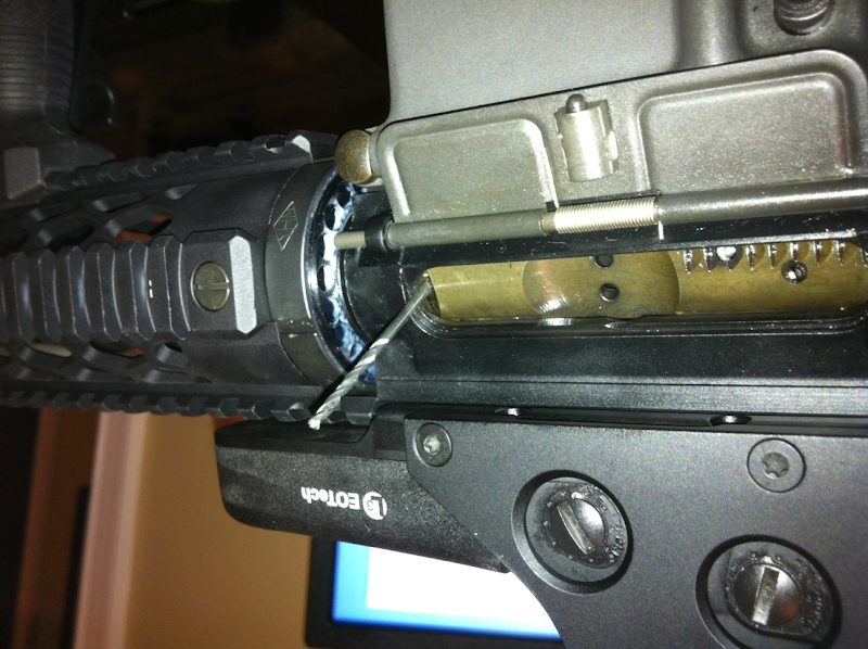
Ideally, your looking for a gap of .084″ between the face of the carrier and face of the barrel extension when the hammer is released. Gap bigger than this, and not only can the cycle rate increase dramatically, but you can into problems with the bolt not fully locked at ignition isntead. If the gap decreased under .084″, then as the hammer is coming down on the FP, although you may not have bolt bounce, the carrier forward closing force is lost from the contact to the barrel extension already completed, and this increases cycle rate as well.
So number #45 drill bit is .082″ and works as a go gauge.
#44 is .086″ and works as a no gauge gauge instead.
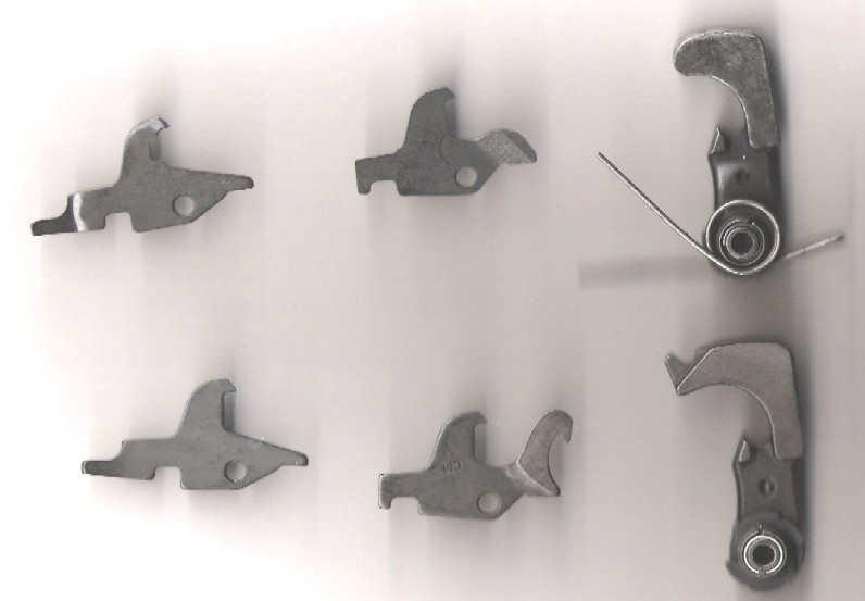
The Selective Fire Lightning Link
One complaint I’ve ever heard about the Lightning Link is that the link converts the firearm to full auto only. This issue was solved by a clever idea that Scott Bell came up with while he was working with John Norrell in about 1990. The solution, which was worked out in a few hours one afternoon, was to use modified parts from an M16A2 fire control kit to control the mode of operation of the Lightning Link.
The M-16A2 trigger group has a pair of disconnects that allow the the selector to use one or the other disconnector during firing. The selective fire kit as Scott Bell and John Norrell developed it, uses one disconnector that has a notch cut into it preventing the LL from tripping it, while the second disconnect does not have this notch and is tripped by the link causing full auto operation as with the standard AR-15 disconnector.
VIDEO INSTRUCTIONS: https://www.youtube.com/watch?v=2HYMg28O4XY&feature=youtu.be
Pics

A potentially NEW way to get selective fire with a Lightning Link!
I have been working with someone else that has come up with another system that provides an selective fire option for the Lightning Link, but this kit uses Modified AR-15 parts. The advantage of this new system is that the Lightning Link could be removed from the lower, or more accurately in the eye of the law, the AR-15 can be removed from the Machine Gun (Lightning Link) and there would not be additional M-16 parts remaining in the AR-15!
Selective Fire Kit for Lightning Link Using AR-15 parts
presented with a little help from Mouseomatic of AR15.com
The best way to begin this page is by referring you to my Lightning Link Page which provides an overview of the Lightning Link. The Lightning Link works in a standard AR-15 as described on the Lightning Link Page and one of the historical disadvantages of the Lightning Link had been that the Lightning Link converted an AR-15 to full auto only (non-selective fire). Scott Bell and John Norrell developed a solution to this problem a few hours back in 1990 by creating a selective fire parts kit using a M16A2 style selector and trigger along with two disconnects as described at the bottom of my Lightning Link Page.
One disadvantage with the selective fire parts kit as developed by John Norrell and Scott Bell, which is sold by Scott Bell to this day, is that the parts used to make the Lightning Link selective fire are M-16 parts and if the Lightning Link was removed from the AR-15, the owner of the AR-15 could find themselves in an legally compromising position for having M-16 parts in an AR-15.
Legal note: as long as a LL is installed in an AR-15, then the AR-15 is part of the machine gun or in this case the AR-15 is a part which is connected to the lightning link. As soon as the LL is removed, the AR-15 is no longer part of the machinegun and all NFA rules would apply. Any M-16 parts that remain in the AR-15 would need to be removed to prevent a potential violation to the National Firearms Act.

In this page, I am going to present a new design for a selective fire parts kit that uses AR-15 parts. The use of AR-15 parts should be obvious as with these modified AR-15 parts, no M-16 parts are ever used in an AR-15 so the Lightning Link can be removed and the rest of the parts can remain in the lower until the next time the registered owner wished to use their Lightning Link!
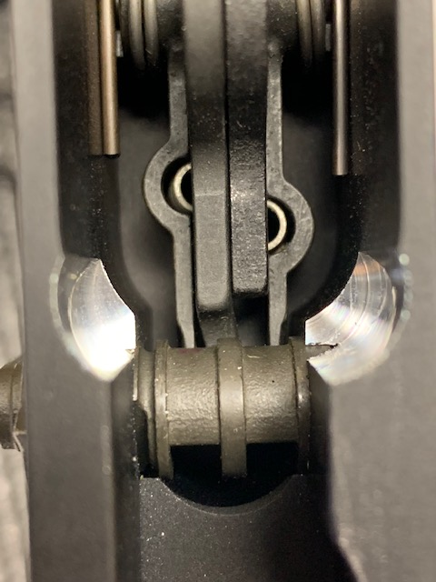
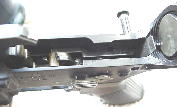
Well, let’s try to discuss this new kit! The selective fire parts kit that I am trying to describe in this web page consists of two modified parts. The first is the disconnector and the second is the selector. When you look at the photo above and to the right that the selector is round inside the receiver pocket and it holds the link up slightly on the disconnector as illustrated. This selective fire parts kit uses this fact to allow the lightning Link to become selective fire with AR-15 parts.
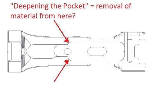
This is accomplished by milling the top of the selector that is exposed in the receiver pocket flush to the top of the receiver pocket ledge when the selector is set in the semiautomatic position. A scribe is then used to mark where the top of the lightning link rests on the disconnector. The disconnector is then removed and an angled notch is cut into the disconnector 0.020-inch wider than the link and .035 deep. With these changes, a Lightning Link will not catch the disconnector when the selector is placed in the “SEMI” position.
To allow the lightning link to work in an third “AUTO” position, the selector will then need to have a groove milled into it with a small detent recess for the third position. As long as the selector retains it’s original diameter this third “AUTO” position will raise the Lightning Link above the notch prepared above allowing the Lightning Link to release the disconnector producing full auto operation when the selector is placed in this position and the weapon is fired with the trigger depressed. The selector will also need to be milled on the bottom edge such as to allow the disconnector to operate, as opposed to being blocked like in the “safe” position.
Another option to create a selector that would provide the “THREE” positions necessary for this kit would be to use a M-16 selector as a starting unit. In this case, the selector would need to be milled flat as described above for the “SEMI” position and the third position could be basically left alone for the “AUTO” position. The extra groves as used with the M-16 Auto Sear could be filled with JB Weld or other means such that the selector would no longer function in an M-16. Using the M-16 selector has some advantages as it would be a simpler modification but it also has the disadvantage as once again we have an M-16 part that we are using in an AR-15.
Quarterbore’s Note: I am planning to write the ATF for clarification if using the an AR-15 selector that is milled for three positions OR using a modified M-16 selector would cause potential non-compliance with National Firearms Act regulations. Given that this system is actually a system designed to allow for selective fire, which would promote safety, and it tries to solve the potential liability issues associated with the traditional options, I hope that the ATF will look favorably on one or both of these options.
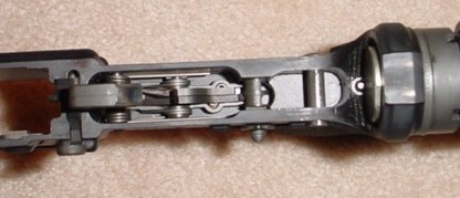
Following are two photos that demonstrate how this selective fire parts kit would look in an AR-15 with a registered Lightning Link.

Given that this selective fire parts kit uses AR-15 parts as opposed to the M16A2 components of Scott Bell and John Norrell’s design this is an interesting alternative!
AR-15 Lowers that will work with a Lightning Link
The following is information from Circuits, a member on AR15.com who is a Class 07 Firearms manufacturer and a Class 02 SOT NFA weapons manufacturer.
To use an SWD Auto Disconnector with an AR-15s it is essential that there is at least an 1/8″ clearance under the takedown pin post for a lightning link to work. All Bushmaster, Sendra, Essential Arms, and some PWA preban lower receiver will work perfect without modification. Some early Colts such as pre-89 SP1 and Sporter II will also work perfect without modification. Later Colts (post-90 to mid 90’s) will also work perfect if the pinned-in sear block is removed.
Most Olympic Arms lower receivers may need internal filing to fit a DIAS or a lightning link. This is because they are not built to the same specifications as the early Colt or bushmaster, and are too narrow by a few 100ths of an inch to fit a DIAS or link. Preban Eagle Arms lowers will fit a DIAS but not a link in Circuit’s experience because it is slightly too large internally to support the link and let it work.
Other lowers such as late-90’s post ban Colts have unmachined web sear block and high shelf while Postban Eagle Arms, Armalite, ASA, and some PWA prebans and all PWA postbans have a high shelf that will need to be milled out to allow a lightning link to work.
Personally (not Quarterbore): I have an Aero and a Noveske for mine.
Advantages of the Lightning Link
1. Relatively inexpensive way to get a full auto M-16
2. Selective fire capability.
3. Can be removed from weapon and stored in a small secure place.
Disadvantages of the Lightning Link
1. Physically can wear out over time.
2. Getting a link to work with a Ciener 22 conversion can prove a difficult challenge.
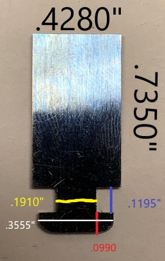
Lightning Link Paddles (per M60Joe)
Material: 1095 Spring Steel, Rockwell C50, Polished, Blue Tempered
I am running .042” thick but other thicknesses are .032” and .050”
I took the below measurements myself – there might be some slight variation between paddles but these should be a good standard.
Tips:
Removal of material at the rear of the receiver is not necessary, although I have seen this done in some instance (picture is from Esox RLL video)
- Check the hammer clearance
- If you don’t have a rear pocket cutout, you might want to check your hammer cocking clearance to prevent possible striking of the RLL.
- RECOMMENDED: One of the things you can to get additional clearance (DO THE LEFT SIDE)
https://www.youtube.com/watch?v=IZHEepHITkY
Original RLL by Max Atchisson (thx Esox!)
Helpful Videos
RLL Overview (must watch!): https://www.youtube.com/watch?v=732Zwy7egu0
Burst Trigger Modification: https://www.youtube.com/watch?v=2HYMg28O4XY&feature=youtu.be
Hammer Modification
https://www.youtube.com/watch?v=IZHEepHITkY
Pictures
Burst Trigger Pack Modification
Pocket relief
FAQS
- Can a semi hammer be used with an RLL?
- Yes, Just look at the disconnector ledge. If it’s wide enough to grab two disconnectors it’ll be fine, if it’s too narrow you may want to look for a different hammer, or get a burst hammer and modify it yourself.
- Can you use a Geissele SSF trigger with the RLL?
- No
Use with 7.62
Modular Lowers (MGI/MCS) for 762
Use with 9mm
CMMG Radial Delayed Blowback 9mm
Pros/Cons by Esox
Not to beat a dead horse, but my here are my opinions on the pros and cons of the RLL after owning one for a little while (note that I do not and have never owned a DIAS or RR):
Pros:
- More robust than anticipated due to the design (when set up and using a protector)
- Stupid easy to swap between hosts with basically no timing issues to deal with
- Robust select fire capability by simple modification to burst kit parts – at the expense of now having M16 FCG parts in your host, so you gotta swap them out as well just like a DIAS
- Wide range of host lowers and chamberings possible (if it is an AR-15 or AR-10 style, you can make it full auto)
- Half the cost of a DIAS
- Its small, portable, and is easily stored safely away
- A metric shit-ton of fun and I think it is a particularly hated item by the BATFE due to its ability to so easily convert a fully legal semi into legal full auto
Cons:
- Need to mill your BCGs to have an SP1 style rear ‘tab’ (0.390″ long, best accomplished by using a modern semi BCG with shrouded firing pin, easy to do on a mill)
- Some host lowers need to have material milled out to allow clearance for the RLL to fit in and move the tiny bit that it does (can be done with a dremel)
- The ‘ears’ are tiny and used to be prone to breaking – the KNS protector eliminated this problem, but I bet they didn’t break much when properly set up so there wasn’t unneeded over travel.
- Upper receivers need to have about 0.040″ ground of the bottom of the rear lug to allow clearance for the RLL when using a protector (20 seconds on bench grinder)
- Limited to single stage MIL-SPEC style triggers (I use ALG QMS triggers, polish them even more, and use a light trigger and disco spring…makes a real nice trigger for cheap)
- Select fire with no M16 FCG parts to allow pick and drop select fire host swapping is still TBD (see other thread, I need to play more with it and I have some ideas on how to make it work another way)
- No reliable .22 rimfire conversion kit yet – I think it is possible and will play with making one if I ever get free time (I have an M11/9mm with Lage 22 kit that runs awesome, so low priority) See below notes by Circuits
- The RLL can get selector rotation wear marks on the lower surface – I have fixed this with a new and improved protector design
- The serial number is just electro-pencil engraved and could be scraped/damaged – I have fixed this with a new protector design
- Hard to find for sale (apparently only 500 or so were ever made)
- Its small and could be easily lost or misplaced.
- Ammo bill
I have been meaning to post some videos of how the link actually works with a cutaway lower and upper. In the meantime, to get a feel for the amount of stress on the link, try this…with your first hand hold the trigger down and cock the hammer back so the disco is holding the hammer. Now with your second hand, take a small screwdriver or pencil and push down on the rear of the disconnector where it sits on top of the spring. Note how little force is required to release the hammer from the disco…that’s the only force on the RLL…even if it was a 50BMG blowback design. (be sure to use your third hand  to prevent the hammer from falling hard onto your receiver to prevent damage).
References
AR15.com (Esox, Circuits,jbntex, Steamedliver, 6-driver, Dano523, amphibian)
AR15.com threads:
Modified semi disconnector for select fire
Special note on .22 per Circuits
a) The problem is that when the trigger is pressed and the bolt carrier is forward, the LL paddle is being forced backward by the disconnector spring, which it’s trying to hold back. With an auto sear, the sear is not under (as much) spring tension in the same carrier and trigger position. The difference is between the disconnector spring against the paddle versus the much weaker auto sear spring. If you’ve got a DIAS or RR to fiddle with, compare the force needed to retard the disconnector versus the force to hold the tripped auto-sear forward.
b) In larger calibers, the buffer spring easily overcomes the force of the disconnector spring and keeps the bolt carrier fully forward. With the 22 conversion kit, the disconnector spring force is comparable to or dominates the force of the kit’s action spring, and tends to pull the conversion bolt back out of battery enough to impede a clean hammer strike.
c) Therefore, if the LL is ever to be made to work reliably with a 22 kit, a trip mechanism which pulls the paddle then releases tension until the next stroke of the conversion bolt will be necessary. Some sort of simple resetting toggle, to get that disconnector spring tension off the paddle/bolt and give the hammer a clean strike.
Successful 22LR RLL by Kyllian
Kyllian is a friend of mine and said he made some improvements since the info below was posted. I will try to make updates when I get the info from him.
https://www.ar15.com/forums/Armory/RLL-with-Ciener-Kit/23-518179/
https://www.youtube.com/watch?v=QpYh0pcvPl8